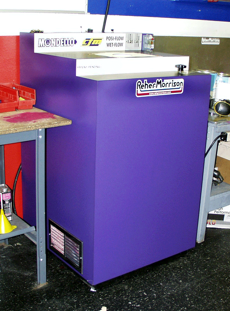
Before florescent wet flow testing the only way to visualize the wet flow in the chamber was with colored water. The colored water would show some of the large wet area's of the chamber and that was about it. Some utilized strobe lights or high speed / slow motion photography as well as other methods in order to better visualize the wet flow vortices and trails in the chamber. The information gathered was not very useful and most people who ventured down this road simply gave up and dismissed the wet flow bench all together. Then came Joe Mondello and Lloyd Creek. At the 2000 AETC conference Joe asked me what I thought of wet flow benches. I told him that I felt they could be a useful tool but gathering any form of useful data from the machines was difficult. They are mainly a visualization tool and a very poor one at that.
Its hard to see what's going on if you cant SEE what's going on!
He told me that Lloyd and himself had been working very hard on that problem and had a way to fix it. If everything worked like they planned they would start building the benches soon and would have the first ones built in about six to eight months. He then asked me if I would be interested in conducting a year of testing with the bench to prove its viability as an research tool. I agreed. One year later A large box was delivered to me at Reher Morrison with this inside.

We then proceeded to make slide plates that closely resembled the runner with all runner angles and taper simulated as close as possible. Brad hall shows how the system works.
We then had to find a way to get rid of the massive amount of fluid (water) that would be shooting out of this thing. I took a bunch of foam tops from Valve boxes and glued them to 1/2 thick piece of plastic that was 5' by 4'. The foam acts as a water separator. When the wet air flow hits the foam the air moves off and the fluid is trapped in the foam. It then runs down on the floor to be mopped up later. It worked better than we could possibly hope for!
I then mounted my flow bench slider plate to the head to simulate the bore. Its 2" thick. I tried longer bores later on and it did not change anything so 2" has proven to be enough to adequately simulate the bore.
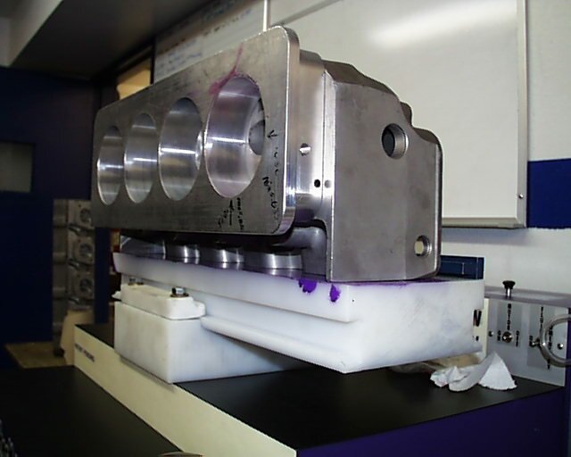
All I had to do then was mount my valve opening apparatus to the back of the slider plate.
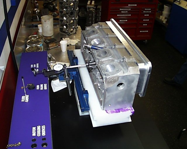
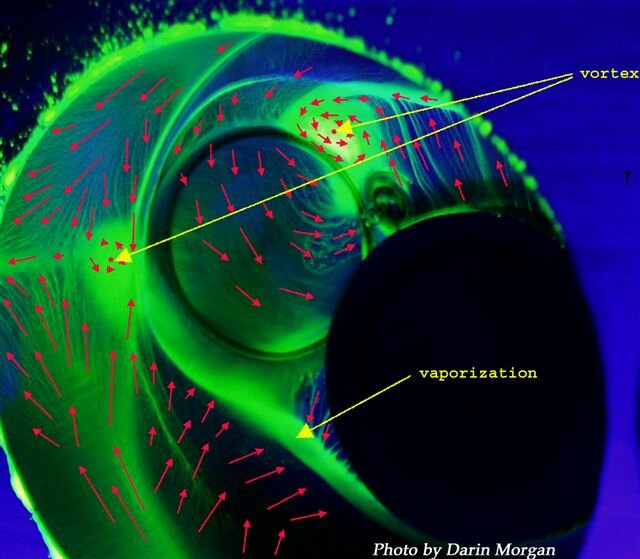
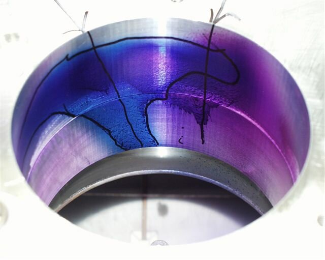
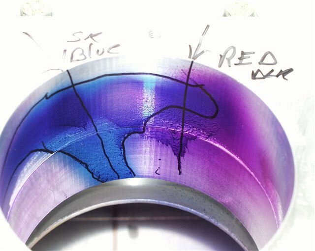
Below are some of the pictures of the Pro Stock testing. The methods I used in order to get these pictures took me many weeks of trial and error because I know absolutely nothing about photography!
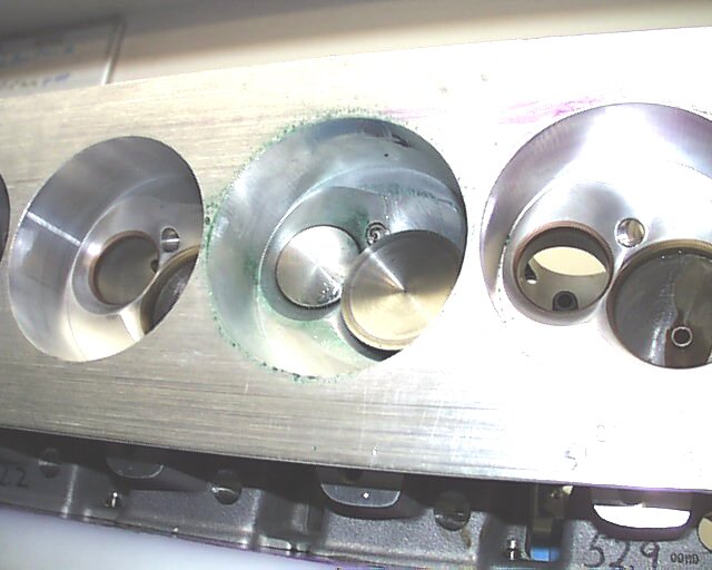
NHRA Pro Stock DRCE cylinder head 2.525 intake valve 1.820 Exhaust.
48cc chamber volume. 4.710 bore diameter.
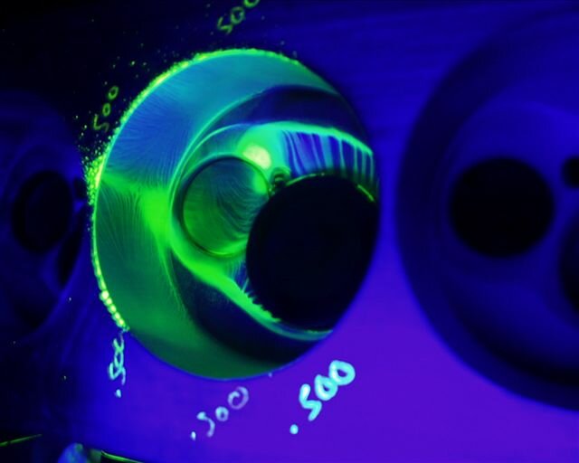
These last two pictures are the same. The last picture took me many days to document the flow path and vortex rotational direction.

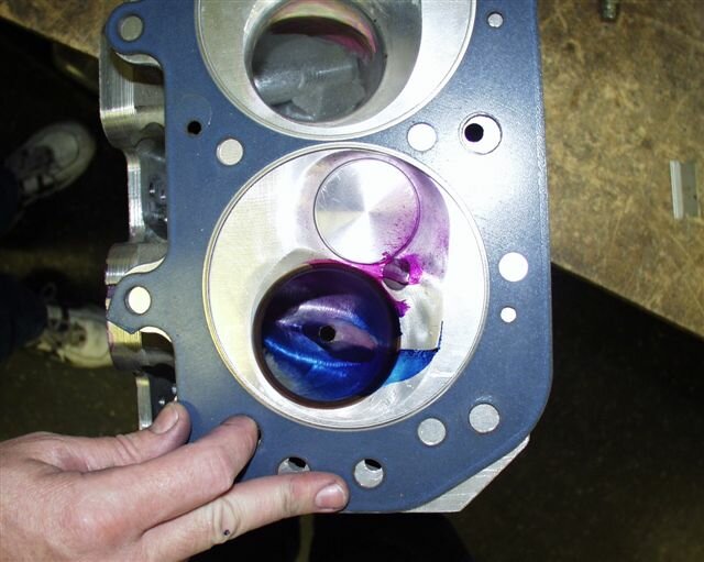
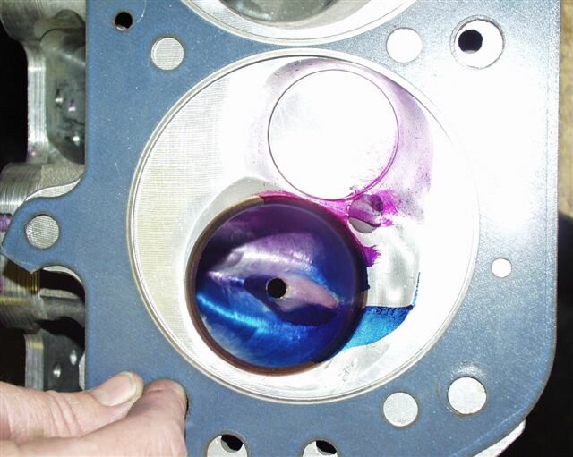
Before the Mondello wet flow bench, this is what we had to do in order to visualize wet flow areas in the induction system and chamber. Spray Dykem in the air and let the port take it in. Any where the dykem left a trail is where the air fuel mixture falls out of suspension. Its very crude to say the least.
.
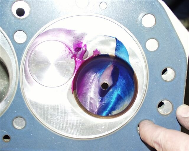
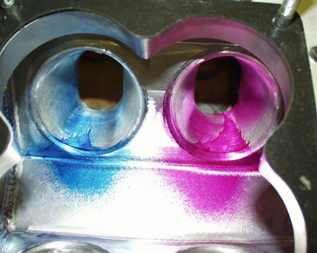
Since this a VERY crude means of wet flow visualization people started to build flow benches and used colored water. It was better but you still could not detect the small variations in the wet flow with in the chamber.
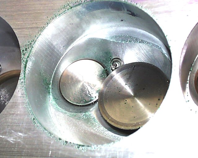
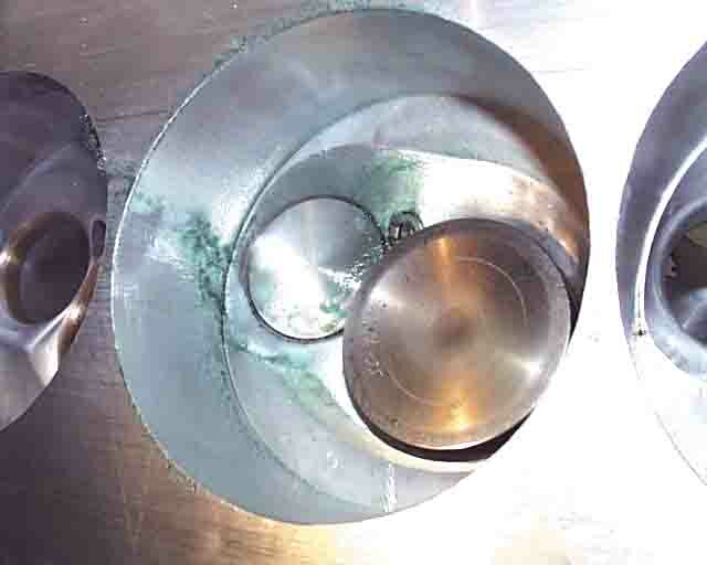
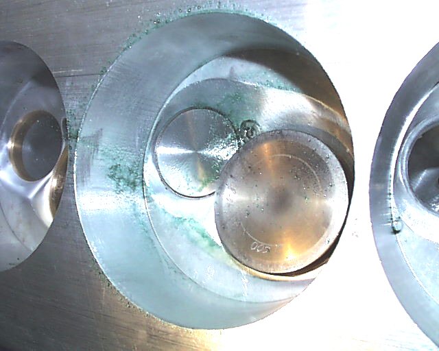
Now, compare the two side by side. Although both pictures below where taken at slightly different angles they where both at .800 valve lift.


Hopefully I can expand this site in the near future to incorporate some video of the wet flow testing.